Industrial Plot Plan Development & Site Zoning Principles
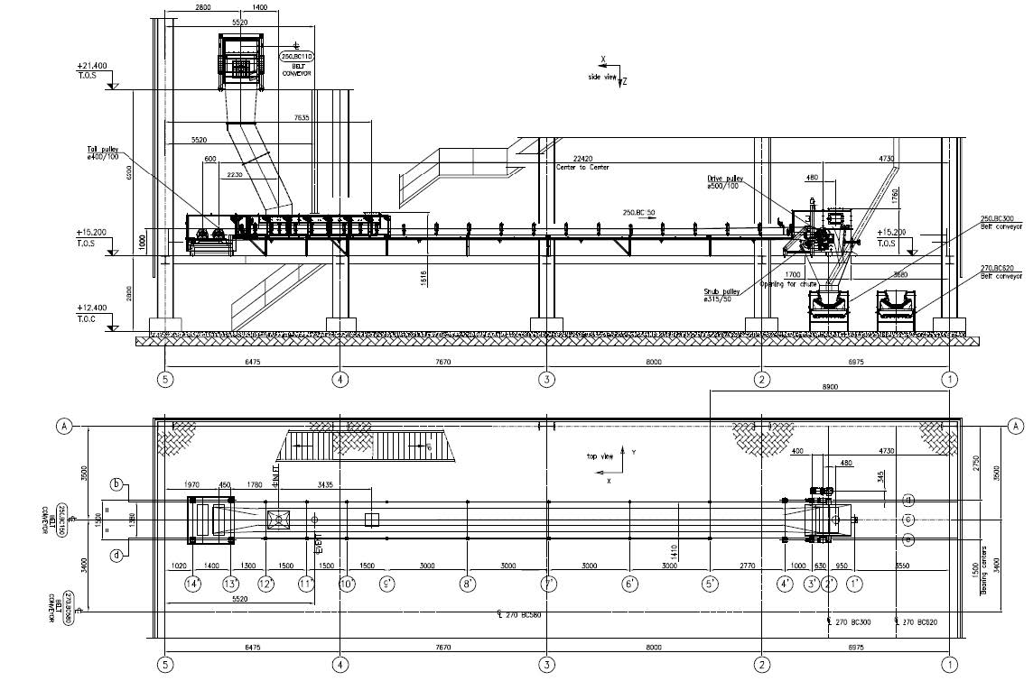
In industrial plant engineering, establishing the spatial framework of a facility is a foundational milestone. Before piping isometrics are drafted, foundations poured, or structural steel erected, project teams must determine how operating units, utility systems, storage tanks, and logistics routes are arranged on site. This strategic spatial allocation is governed by the industrial plot plan.
An industrial plot plan serves as the spatial master plan for an operating facility. By establishing site zoning, defining battery limits, and coordinating logistics routes, the plot plan establishes physical relationships between process areas, utility areas, and support infrastructure. For EPC contractors, plant owners, and engineering consultants, plot plan development ensures that safety separation distances, maintenance access, construction sequences, and future expansion allowances are addressed before detailed discipline design progresses.
Because industrial site layout decisions directly influence capital expenditure, operating efficiency, and life-cycle safety, engineering teams frequently partner with Port AI Engineers for professional Industrial Plant Layout Design Services. These structured workflows deliver optimized plot plans and equipment layouts that balance regulatory criteria, operational workflows, and multi-discipline plant design coordination from early concept studies through construction execution.
1. What Is an Industrial Plot Plan?
An industrial plot plan is an engineering drawing defining the overall site arrangement and spatial boundaries of major facilities, process blocks, utility areas, storage facilities, buildings, and transportation networks within a property. It illustrates how the industrial site layout functions as an integrated system, linking process operations with civil infrastructure, environmental containment, and external distribution networks.
A comprehensive plot plan delineates key physical assets across the property, including process units, storage tank farms, power generation blocks, water treatment facilities, substations, control rooms, administrative offices, workshops, flare systems, and waste handling areas. It also establishes external interfaces, such as highway tie-ins, railway sidings, marine jetties, and pipeline corridors.
A plot plan differs fundamentally from an equipment layout or General Arrangement (GA) drawing. While an equipment layout or GA drawing focuses on physical placement, nozzle elevations, and structural mounting of individual machines within a specific unit, a plot plan operates at the macro site level, allocating spatial footprints, coordinating interconnecting pipe rack corridors, and establishing property boundary clearances without detailing equipment internals.
2. Plot Plan vs. Plant Layout vs. GA Drawing: Spatial Hierarchies
In industrial plant engineering, spatial design progresses across multiple levels of resolution. Understanding the distinction between a plot plan, an overall plant layout, and a General Arrangement drawing prevents scope confusion and ensures smooth discipline coordination:
Industrial Plot Plan (Macro Level)
The plot plan establishes the site-wide spatial master plan, mapping overall boundaries, functional zoning, battery limits, main access roads, rail connections, stormwater basins, and central pipe rack corridors. It serves as the primary coordination document between the owner, municipal authorities, civil contractors, and environmental regulators.
Plant Layout & Unit Layout (Meso Level)
Within individual process units or utility blocks, plant layout engineering determines the spatial arrangement of equipment groups, pump bays, heat exchanger banks, and local pipe racks. Plant layout design coordinates process flow sequences, maintenance clearance zones, and structural steel bents across disciplines.
General Arrangement (GA) Drawing (Micro Level)
At the detailed execution level, General Arrangement drawing deliverables provide orthographic plans, elevations, and sections showing exact equipment dimensions, baseplate locations, nozzle orientations, and structural levels. As explored in our technical guide on industrial GA drawing anatomy, GA drawings translate layout strategy into coordinated multi-view engineering deliverables that guide equipment placement and detailed installation planning.
Project practices vary, and the boundary between an overall plot plan and unit plant layouts is often refined iteratively across project stages from conceptual design to Front-End Engineering Design (FEED).
3. Site Zoning Principles in Industrial Facilities
Site zoning divides an industrial property into distinct functional sectors based on operational compatibility, hazard levels, environmental exposure, and logistics flow. Disciplined zoning segregates incompatible activities while clustering interdependent operations:
- Process Areas (ISBL): Central cores accommodating reactors, separation columns, furnaces, and operating equipment.
- Utility Areas: Centralized generation blocks—boilers, cooling towers, air compressors, and water treatment.
- Storage Areas: Bulk tank farms, pressurized spheres, cryogenic storage, and product warehouses.
- Administration & Support: Non-hazardous offices, central control rooms, laboratories, and gatehouses.
- Maintenance & Fabrication: Central workshops, spare parts stores, and staging laydown yards.
- Electrical Corridors: High-voltage switchyards, unit substations, and motor control centers (MCC).
- Loading & Logistics: Truck loading racks, rail terminals, and weighbridges near boundaries.
- Circulation & Buffers: Perimeter roads, emergency access lanes, security setbacks, and greenbelts.
Zoning decisions depend on local meteorological and topographical conditions. Control rooms and offices are typically positioned upwind of process units relative to prevailing winds, minimizing toxic gas exposure during an upset. Flammable storage and wastewater ponds are placed downwind and topographically lower where feasible, containing potential vapors or spills.
4. Equipment Areas and Major Plant Spatial Relationships
The physical arrangement of equipment areas on a plot plan must reflect the logical sequence of plant operations, from incoming feedstocks through conversion to product dispatch. Incoherent arrangements cause excessive interconnecting piping lengths, higher pressure drops, elevated pumping power, and operational complexity.
Process Flow Alignment: Process units follow an orderly progression. Locating consecutive blocks adjacent minimizes intermediate piping runs, heat loss, and alloy piping costs. Where gravity flow is required, plot plans incorporate terrain slopes or structural elevations.
Utility Placement Strategy: Utility generation blocks—boilers, compressors, and cooling towers—are positioned near the center of consumption. Centralized utility placement reduces main header lengths and line sizes, whereas peripheral placement increases distribution costs.
Separation of Incompatible Facilities: Fired heaters, incinerators, and flare stacks represent ignition sources and must be segregated from flammable storage tanks, relief points, and hydrocarbon handling areas. Similarly, cooling towers produce moisture plumes that must not drift toward high-voltage switchyards or control rooms.
5. Battery Limits and Plant Interfaces
The concept of battery limits is central to industrial plot planning, establishing boundary lines that define engineering scope, physical jurisdiction, and contractual handoffs across complex facilities.
ISBL vs. OSBL Definitions: Industrial facilities are divided into Inside Battery Limits (ISBL) and Outside Battery Limits (OSBL). ISBL encompasses dedicated process units where chemical conversion occurs. OSBL encompasses supporting infrastructure, including offsite tankage, utility generation, wastewater treatment, administration buildings, and interconnecting pipe racks.
Tie-In Points and Interface Control: A plot plan defines the physical location of battery limit tie-in stations where process lines, steam headers, fuel gas feeds, cooling water loops, instrument air manifolds, and power feeders enter or exit each unit, ensuring seamless coordination between EPC consortia, licensors, and discipline leads.
Battery limit definitions are project-specific. Contracts establish precise coordinates, isolation valve boundaries, flange ratings, and terminal points for all connections at the battery limit line.
6. Access Roads, Maintenance Access and Logistics Movement
An industrial facility cannot function safely without a hierarchical transportation network. Inadequate traffic planning results in congested roadways, impeded emergency response, and severe delays during planned plant turnarounds.
Road Hierarchy and Circulation: Plot plans establish a structured road network:
- Primary Arterial Roads: Paved perimeter roadways dividing major blocks, accommodating heavy haulers, cranes, and fire tenders.
- Secondary Service Roads: Access lanes connecting units and utility yards for maintenance vehicles and deliveries.
- Operational Aisles: Dedicated walkways for operator rounds, forklift transit, and local valve access.
Maintenance and Turnaround Rigging: Major maintenance requires dedicated laydown areas and crane outrigger pads adjacent to heavy vessels and heat exchangers. Shell-and-tube exchangers require corridors to pull tube bundles, while compressors and pumps require crane clearance and laydown zones for motor removal.
Design teams must not assume universal road widths or turning radii; dimensional requirements depend on fleet specifications, crane footprints, and municipal regulations.
7. Pipe Rack and Utility Corridor Planning
Pipe racks and utility corridors represent the circulatory backbone of an industrial plant, conveying process fluids, steam, cooling media, electrical power, and control signals across the site. Plot planning establishes primary geometric routing corridors before detailed piping design begins.
Pipe Rack Layout Architecture: Most complex plants utilize a spine-and-comb pipe rack configuration. A central pipe rack spans the main facility axis, connecting utilities, process units, and storage tank farms. Secondary transverse racks branch out perpendicularly into process units. This orthogonal layout optimizes structural steel design, simplifies piping routing, and creates standardized expansion corridors.
Underground vs. Above-Ground Corridors: Plot planning coordinates spatial allocation between overhead pipe racks and underground corridors. High-pressure steam, hazardous hydrocarbons, and maintenance-intensive lines run on overhead racks for visual inspection. Conversely, cooling water headers, raw water feeds, firewater loops, and oily sewers typically run underground to preserve surface space and prevent freezing.
Coordinating utility corridors on the plot plan prevents congestion during subsequent 3D Piping Design Services, ensuring duct banks, instrument trenches, and storm sewers do not clash beneath roadway crossings.
8. Fire Access Considerations, Safety and Drainage Integration
Safety and environmental risk management are central drivers of industrial plot plan development. A well-designed plot plan incorporates passive safety principles to prevent an upset in one unit from escalating into a domino event across adjacent areas.
Separation and Fire Exposure: Separation distances between process blocks, tank farms, and occupied buildings are established based on consequence modeling, thermal radiation thresholds, and blast overpressure contours. Tanks holding flammable liquids are surrounded by containment dikes (bund walls) capable of holding full tank volumes during a rupture.
Fire Access Considerations: Plot plans ensure major units feature access roads from at least two opposite directions, allowing emergency responders to approach upwind regardless of wind direction. Perimeter firewater mains, hydrants, and monitor stations are spaced along peripheral roads outside blast or radiation zones, ensuring reliable water supply.
Drainage Considerations and Environmental Containment: Industrial sites require segregated drainage systems: unpolluted stormwater runoff, potentially contaminated surface water, and oily chemical sewers. Critical drainage considerations involve coordinating site grading elevations, catch basins, interceptors, and retention ponds to prevent contaminated effluent from overflowing during heavy storms.
Engineering teams must not rely on generic rules of thumb; separation criteria must be evaluated against applicable local fire codes, environmental regulations, corporate engineering standards, and site-specific risk assessments.
9. Plot Plan Coordination Workflow: From Concept to Approval
Plot plan development is an iterative, multi-discipline engineering process that evolves across design gates as project definitions mature:
1. Site Data & Boundary Survey
Gather topographical surveys, soil borings, wind roses, flood data, property boundaries, and utility tie-in points.
2. Process Definition & Balances
Review PFDs, mass balances, utility balances, and equipment lists to establish unit capacities and vessel counts.
3. Preliminary Functional Zoning
Establish high-level zones (process, storage, utilities, administration) based on prevailing winds, logistics, and topography.
4. Logistics & Road Framework
Lay out perimeter roads, security gates, truck racks, rail sidings, and emergency access pathways.
5. Equipment Footprint Allocation
Allocate footprint envelopes for each operating unit, sizing blocks for equipment spacing and maintenance clearances.
6. Pipe Rack & Corridor Routing
Route pipe rack spines and feeder racks, aligning overhead rack tiers with underground utility trenches.
7. Multi-Discipline Reviews
Conduct spatial reviews with process, civil, structural, piping, electrical, safety, and operations teams.
8. Revision Control & Release
Apply design updates, revision clouds, and signatory approvals to issue baseline plot plans.
10. Common Problems in Industrial Plot Plan Development
Plot plan errors identified late in design or during construction are among the costliest mistakes an engineering team can encounter. Common design pitfalls include:
- Neglecting Future Expansion: Designing compact layouts without allocated corridors or footprint allowances for future trains, forcing expensive shutdowns during expansions.
- Inadequate Maintenance Access: Placing equipment too close to pipe racks, preventing crane access or bundle pulling without dismantling piping.
- Ambiguous Battery Limits: Unclear ISBL/OSBL scope boundaries, causing misaligned rack elevations or omitted tie-in valves.
- Underground Utility Congestion: Routing electrical duct banks beneath process gravity sewers or firewater mains, creating constructability clashes and maintenance hazards.
- Ignoring Natural Topography: Siting containment basins on elevated terrain or positioning process units requiring gravity drain in depressions prone to pooling.
- Conflicting Road Logistics: Single-access roads blocked by maintenance cranes, cutting off emergency escape routes or fire tender access.
- Drawing Revision Disconnects: Late process modifications not propagated into civil site models, resulting in undersized foundation plots during site preparation.
11. Industrial Plot Plan & Plant Layout Services at Port AI Engineers
Port AI Engineers delivers engineering design and spatial coordination solutions to EPC contractors, industrial plant owners, and engineering consultants. Our layout specialists develop robust, compliant, and cost-effective industrial plot plans tailored to complex process facilities, power plants, manufacturing complexes, and greenfield developments.
Through our specialized Industrial Plant Layout Design Services, we support engineering programs across all project stages:
- Master plot plan drafting and conceptual site layout optimization for greenfield project planning.
- Functional site zoning, hazard segregation studies, and property boundary interface management.
- Equipment arrangement modeling and multi-view coordination via General Arrangement Drawing Services.
- Central pipe rack corridor allocation and utility routing coordination aligned with 3D Piping Design Services.
- Digitization and modernization of legacy site plots into layered CAD models through CAD Conversion Services.
- Strict engineering revision governance, coordinate datum alignment, and master drawing register management.
Our engineering team emphasizes constructability, operational ergonomics, and disciplined plant design coordination, ensuring your site layout serves as an enduring foundation for capital efficiency and life-cycle safety.
Conclusion
An industrial plot plan is the foundational spatial architecture governing how an industrial facility operates, expands, and protects personnel. By translating process chemistry and mechanical requirements into balanced functional zones, structured road networks, clear battery limits, and organized pipe rack spines, the plot plan establishes the physical framework upon which all subsequent discipline engineering depends.
Successful plot plan development balances immediate construction economy with multi-decade operational reliability. Avoiding common pitfalls—such as neglected turnaround clearances, uncoordinated underground corridors, or ambiguous interface boundaries—protects projects from costly construction field rework and operational bottlenecks.
Whether designing a new greenfield facility, expanding existing unit battery limits, or modernizing site documentation, explore our Industrial Plant Layout Design Services or contact the plant engineering specialists at Port AI Engineers today.
More from Port AI Engineers
Explore related engineering and CAD insights.