Anatomy of an Industrial General Arrangement (GA) Drawing: Plans, Elevations & Sections
In industrial plant engineering, translating conceptual process designs into physical operating facilities is a critical challenge for project teams. While process flow diagrams (PFDs) and piping and instrumentation diagrams (P&IDs) establish thermodynamic and mechanical control logic, they communicate virtually nothing about physical space, elevation, or orientation. Bridging the gap between schematic logic and physical reality requires robust spatial documentation centered around the industrial General Arrangement drawing.
A General Arrangement drawing—universally known as a GA drawing, equipment arrangement drawing, or equipment layout drawing—serves as the primary spatial master plan for an operating facility. By defining the physical positions of process vessels, rotating equipment, structural steel modules, pipe racks, and access ways, GA drawings provide an authoritative source of truth across engineering disciplines. For EPC contractors, engineering consultants, plant owners, and fabrication teams, these engineering drawings are fundamental to ensuring that physical equipment and structures fit together without spatial clashes or maintenance obstructions.
Because industrial facilities encompass intricate mechanical, civil, and structural interfaces, plant teams frequently engage Port AI Engineers for professional General Arrangement Drawing Services. These specialized workflows deliver coordinated 2D plant GA drawing packages and equipment layouts that align engineering teams from early concept studies through construction execution.
1. What Is an Industrial General Arrangement Drawing?
An industrial General Arrangement drawing is a multi-view technical drawing defining the physical location, orientation, overall dimensions, and spatial relationships of major equipment, structures, and auxiliary systems within a plant area. Unlike single-discipline detail drawings, a plant GA drawing functions as an integration deliverable, illustrating how mechanical equipment, civil structures, piping corridors, and electrical systems co-exist in three dimensions.
A GA drawing differs fundamentally from detailed fabrication drawings. Fabrication drawings—such as vessel shop prints, structural steel details, or piping isometrics—focus on component manufacturing, detailing weld symbols, bolt schedules, and plate thicknesses. In contrast, an equipment arrangement drawing operates at the system level, depicting equipment as geometric envelopes with boundary dimensions, nozzle orientations, mounting baseplates, and primary connection points without detailing minor internals.
The primary purpose of a GA drawing is spatial coordination. It communicates physical arrangement so civil teams design foundations, structural engineers size pipe racks, piping designers route lines, and electrical engineers allocate cable trays. No single GA drawing serves every project phase or discipline; rather, GA drawings evolve across project lifecycles from preliminary concept plots to detailed construction layouts.
2. What Information Does a GA Drawing Typically Show?
While specific content varies depending on facility type, engineering discipline, and project phase, professional engineering drawings typically incorporate several core informational categories:
- Equipment Placement & Identification: Outlines of major mechanical equipment—columns, reactors, tanks, pumps, exchangers, and compressors—labeled with tag numbers matching P&IDs.
- Major Dimensions & Centerlines: Overall boundary dimensions, footprint sizes, centerline coordinates, and spacing tied directly to established plant grids.
- Elevations & Vertical Datums: Finished floor levels (FFL), top of concrete (TOC), top of steel (TOS), nozzle centerlines, and platform elevations referenced to plant datum.
- Access & Maintenance Envelopes: Dedicated clearance envelopes for bundle pull zones, pump motor removal, tube replacement, and crane lifting paths.
- Platforms & Structural Elements: Operating decks, safety cages, vertical ladders, egress stair towers, and handrails where applicable.
- Piping Interfaces & Battery Limits: Primary pipe rack corridors, process headers, interface nozzle locations, and battery-limit lines where appropriate.
- Reference Grids & Orientation: Alphanumeric structural grid lines, coordinates, and plant north or true north indicators.
- Drawing Notes & Section References: Callouts linking to associated section cuts, detail sheets, vendor drawings, and piping layout documents.
Engineering teams tailor detail to drawing scope; overloading a GA drawing with minor details obscures critical equipment placement and spatial clarity.
3. GA Plans, Elevations and Sections
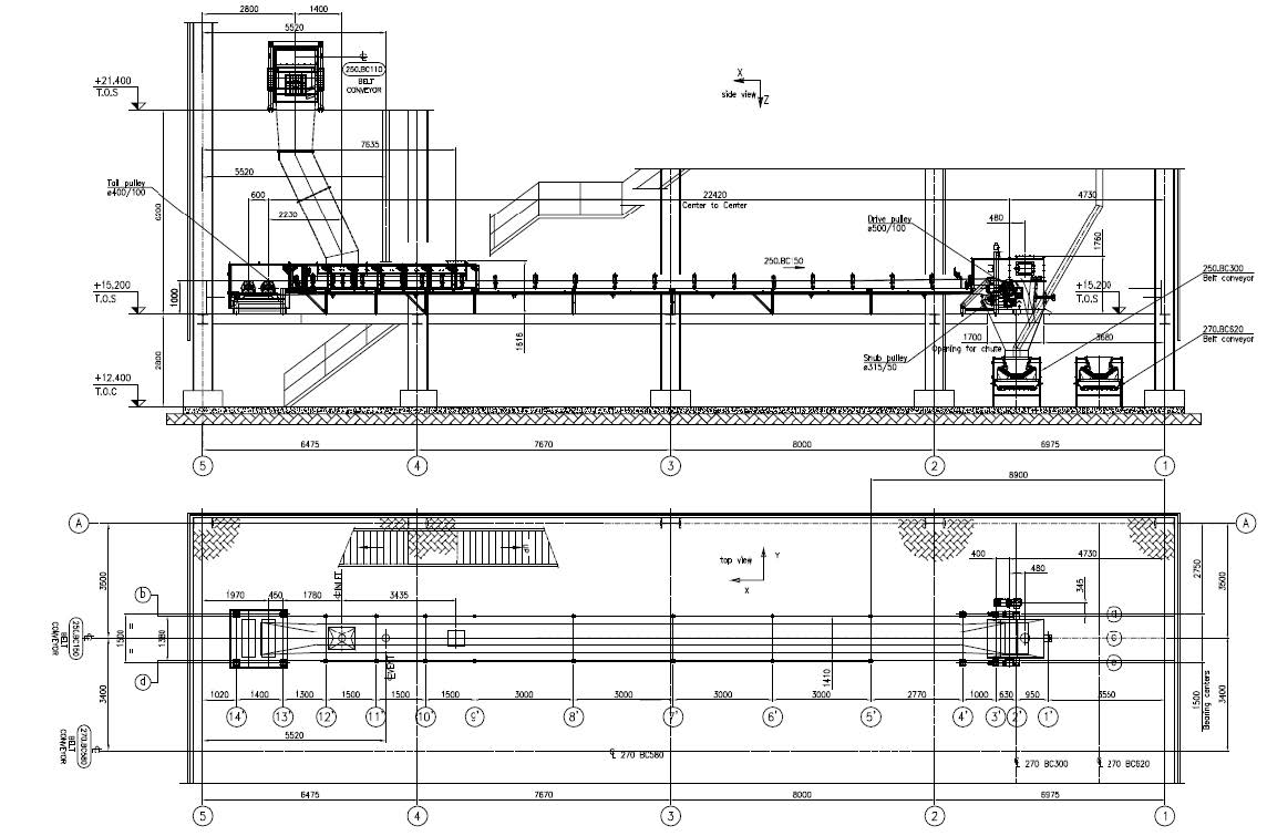
To define three-dimensional space on two-dimensional media, an industrial General Arrangement drawing employs orthographic projection. The core anatomy of a GA drawing package revolves around three coordinated view types: plans, elevations, and sections.
A. The GA Plan View
The GA plan is an orthographic top-down projection of an operating level. It defines equipment arrangement in the horizontal (X and Y) plane, locating centerlines of vessels, pump skids, and columns relative to structural grids or coordinates.
In multi-level facilities, separate GA plan sheets are prepared for each operating floor, mezzanine, and roof level, illustrating horizontal spacing, access aisles, forklift roadways, egress paths, and battery limits.
B. The GA Elevation View
The GA elevation is a vertical orthographic view looking horizontally at the facility from exterior viewpoints, typically designated by direction (e.g., North Elevation or Looking South). Elevation views communicate the vertical (Z) dimension, revealing equipment heights, skirt heights, support structures, framing tiers, and clear heights beneath pipe racks.
Elevation views illustrate vertical alignment between elevated equipment—such as condensers mounted above reflux drums—ensuring that process hydraulics and gravity flow requirements are viable.
C. The GA Section View
The GA section represents an imaginary vertical cut through the plant, slicing through equipment, pipe racks, and buildings to reveal internal spatial relationships hidden in exterior views. Section cuts are identified on plan views by cutting-plane lines with directional arrows (e.g., "Section A-A").
Section views are indispensable for resolving congested multi-level spaces, showing vertical clearances between stacked heat exchangers, pipe rack tiers, beam penetrations, valve operating heights relative to grating, and drainage trenches.
4. Equipment Placement and Spatial Coordination
Equipment placement on a General Arrangement drawing balances operational efficiency, safety separation, constructability, and plant maintainability. In professional engineering practice, placing equipment is never simply a matter of fitting components into available footprint.
Operational and Maintenance Access: Industrial equipment requires planned clearance for servicing and overhauls. Shell-and-tube exchangers require clearance to pull tube bundles. Pumps need laydown space and vertical clearance for motor and impeller rigging. Compressors demand crane access for casing removal. A well-constructed GA drawing delineates these maintenance envelopes with dashed boundary lines, preventing piping or structural steel from encroaching upon critical service corridors.
Multi-Discipline Spatial Coordination: Equipment placement establishes boundary conditions for downstream disciplines. Civil engineers utilize equipment footprints and operating loads to design foundations. Electrical teams verify routing corridors for switchgear and cable trays. Piping engineers rely on equipment positions to establish pipe rack orientations and process line routing.
Drafting teams must not invent arbitrary numerical values for clearances or spacing. Specific clearance dimensions depend on equipment manufacturer guidelines, client engineering standards, ergonomic requirements, and adopted local safety codes.
5. Dimensions, Elevations and Reference Information
Dimensions and reference markers transform a visual layout into an actionable engineering coordinate system, ensuring contractors locate equipment accurately on site.
Coordinate Datums and Reference Grids: Industrial facilities establish a plant coordinate system based on a benchmark datum. Structural column grids provide local reference lines. On a GA plan, equipment centerlines are dimensioned directly from these grid lines, ensuring civil surveyors establish anchor bolt locations accurately before equipment delivery.
Elevation Datums: Vertical dimensions on GA drawings are expressed as absolute elevations relative to plant datum rather than incremental heights. Drawings specify key reference planes, including finished grade, top of concrete foundation (TOC), top of steel beam (TOS), and equipment centerline elevations (CL). Unified datums prevent cumulative measuring errors during construction.
Dimensioning Hierarchy: General Arrangement drawings focus on primary reference dimensions: overall battery limit boundaries, grid spacing, equipment centerline coordinates, and major nozzle centerlines. Detailed equipment fabrication dimensions are omitted to maintain drawing legibility.
6. GA Drawings and Piping Design
The General Arrangement drawing and piping design share a reciprocal relationship. In process plants, piping represents a major portion of capital expenditure; consequently, equipment placement directly influences piping economy and operational reliability.
Nozzle Locations and Line Routability: Equipment arrangement dictates the routing complexity of process lines. Placing pump suction nozzles close to tank drain outlets minimizes suction line length and reduces pressure drop, preventing pump cavitation. Conversely, uncoordinated equipment placement forces complex piping loops, excessive fittings, and elevated nozzle loads that complicate stress analysis.
Piping GA Drawings vs. Equipment GAs: While equipment GA drawings establish machinery footprints and foundations, piping GA drawings map major process headers, pipe racks, control valve manifolds, and support locations. These drawings coordinate pipe rack elevations, battery-limit tie-ins, and expansion loop clearances.
GA drawings do not replace detailed piping isometrics or comprehensive 3D models. A piping GA communicates collective spatial arrangement, whereas piping isometric drawings provide fabrication-level spool dimensions, weld lists, and cut lengths required by pipe fitters.
7. GA Drawings and 3D Plant Design
In modern industrial project execution, General Arrangement drawings are typically generated directly from coordinated multi-discipline 3D plant design environments.
Model Coordination and Drawing Extraction: Within contemporary 3D plant design software, mechanical equipment, structural steel, concrete foundations, and piping corridors are modeled concurrently in a shared digital space. Once the 3D model reaches design maturity gates, drawing specialists define orthographic cutting planes to extract plan views, elevations, and section drawings directly from the model database.
Dynamic Consistency Across Views: Extracting GA drawings from 3D models ensures spatial integrity across views. If an equipment nozzle location or foundation pedestal is modified in the 3D model, associated plan, elevation, and section drawings can be updated systematically, eliminating discrepancies between drawing sheets.
However, automated extraction alone does not produce an engineering-grade drawing. Model-extracted linework requires disciplined 2D CAD drafting cleanup: applying standardized layer styles, positioning legible dimension strings, optimizing annotations, and structuring revision title blocks. Modern plant design marries 3D spatial modeling with rigorous 2D drafting presentation.
8. Common Problems in Industrial GA Drawings
In industrial projects, drawing coordination errors on GA deliverables frequently lead to field rework, fabrication clashes, and construction delays. Common documentation discrepancies include:
- Outdated Equipment Geometry: Equipment models based on preliminary quotes rather than certified vendor prints, causing mislocated nozzles or incorrect baseplates.
- Inconsistent Dimensions: Centerline coordinates or boundary dimensions on a plan view that contradict matching elevation or section callouts.
- Missing or Ambiguous Elevations: Omission of critical vertical datums—such as top of concrete, underside of pipe rack steel, or platform grating levels.
- Unclear Section References: Section callout arrows on plan sheets referencing non-existent section cuts, missing detail numbers, or incorrect sheets.
- Conflicting Equipment Tagging: Equipment tags that contradict P&IDs, mechanical line lists, or process equipment datasheets.
- Overlooked Maintenance Envelopes: Failing to show tube pull zones, pump removal paths, or valve access corridors, leading to unmaintainable installations.
- Discipline Coordination Gaps: Structural columns clashing with foundation pedestals, or cable trays routed through piping corridors without inter-discipline reviews.
- Drawing Revision Disconnects: 3D model changes failing to propagate into issued 2D drawing sets, leaving outdated prints on site.
9. GA Drawing Review and Quality Checks
Quality assurance for General Arrangement drawings requires a structured engineering review process prior to formal drawing release:
1. Scope and Drawing Purpose Verification
Verify drawing issue purpose (e.g., Issue for Review, Issue for Design, or Issue for Construction) and confirm battery limit boundaries.
2. Equipment Tag and Datasheet Cross-Check
Audit equipment tags against current P&IDs, equipment lists, and certified vendor drawings to confirm dimensions and nozzle schedules.
3. Grid and Dimension Verification
Verify that equipment centerlines tie back to primary structural grids and dimension strings add up consistently across views.
4. Datum and Elevation Reconciliation
Confirm finished grade, top of concrete, top of steel, and centerline elevations across views against project datum.
5. Multi-View Projection Alignment
Cross-reference plan, elevation, and section views to verify identical spatial representation and confirm section arrows match target details.
6. Maintenance and Egress Corridor Audit
Verify maintenance envelopes, tube pull areas, crane access corridors, and safety egress paths are free of structural obstructions.
7. Inter-Discipline Coordination Review
Coordinate drawing overlays with civil, structural, piping, electrical, and HVAC teams to eliminate clashes at battery limits and interfaces.
8. Revision Control and Release Governance
Record revisions with formal clouding, revision block descriptions, signatory approvals, and logging in the master drawing register.
Systematic quality checks ensure that issued GA drawings serve as reliable baselines, preventing costly field modifications and structural clashes.
10. General Arrangement Drawing Services at Port AI Engineers
Port AI Engineers delivers comprehensive CAD drafting and engineering design coordination services to EPC contractors, industrial facility owners, and engineering consultants. Our plant design team specializes in developing clear, standardized, and revision-controlled General Arrangement drawings tailored to complex manufacturing, chemical, and energy facilities.
Through our specialized General Arrangement Drawing Services, we support engineering programs with:
- Preparation of equipment arrangement drawings and plant GA drawings.
- Multi-view GA development incorporating coordinated plans, elevations, and detailed section cuts.
- Piping GA drawing drafting, pipe rack routing coordination, and interface nozzle layout management.
- Integration with broader Industrial Plant Layout Design Services to optimize process unit spacing and battery limit coordination.
- Coordinated drafting support aligned with 3D Piping Design Services for seamless model-to-drawing extraction.
- Digitization and modernization of legacy paper plots into layered, editable CAD formats via CAD Conversion Services.
- Strict drawing revision management, title block standardization, and drawing register coordination.
Our engineering-driven drafting workflows emphasize geometric precision, inter-discipline alignment, and strict adherence to client drafting standards, delivering dependable engineering deliverables for procurement and construction execution.
Conclusion
An industrial General Arrangement drawing is an indispensable pillar of plant engineering design. By unifying equipment placement, structural steel grids, piping corridors, and maintenance clearances across coordinated plan, elevation, and section views, GA drawings bridge the gap between schematic process intent and physical plant construction.
Whether developed directly through 2D drafting methods or extracted from coordinated 3D plant design software, successful GA drawings depend on rigorous dimensioning, consistent datum referencing, and systematic quality reviews. Clear, accurate equipment arrangement drawings minimize construction clashes, streamline multi-discipline handoffs, and protect ongoing facility operability.
To develop new plant GA drawings, update existing equipment arrangements, or convert legacy layouts into structured CAD deliverables, explore our General Arrangement Drawing Services or contact the engineering design team at Port AI Engineers today.
More from Port AI Engineers
Explore related engineering and CAD insights.