Industrial Fire Evacuation Drawing Standards: Egress Mapping, Symbols & Best Practices
In industrial manufacturing plants, chemical processing facilities, high-bay distribution centers, and multi-discipline complexes, emergency preparedness depends on rapid, decisive communication. When an incident occurs—whether a fire, toxic gas leak, or chemical spill—personnel must make immediate egress decisions under acute stress. Machinery noise, smoke, power interruptions, and adrenaline significantly impair cognitive processing. In these critical moments, an accurate, legible industrial fire evacuation drawing serves as an indispensable visual guide for life safety and emergency response.
An effective fire evacuation drawing is a functional life-safety schematic that translates complex facility geometry into actionable spatial guidance. For plant owners, EPC contractors, safety engineers, and documentation teams, maintaining drawing accuracy is a core operational priority. If an evacuation map displays obsolete layouts, sealed corridors, or misplaced equipment, it creates hazardous confusion during an evacuation. While facility-wide industrial fire evacuation planning establishes broader safety procedures, drills, and management policies, physical drawings displayed throughout a plant communicate real-time egress pathways when seconds matter.
To ensure drawings remain up to date and aligned with physical site conditions, engineering organizations frequently partner with Port AI Engineers for professional Fire Evacuation Drawing Services. These specialized workflows convert intricate facility layouts into standardized, high-contrast evacuation drawings engineered for demanding industrial environments.
1. What Is an Industrial Fire Evacuation Drawing?
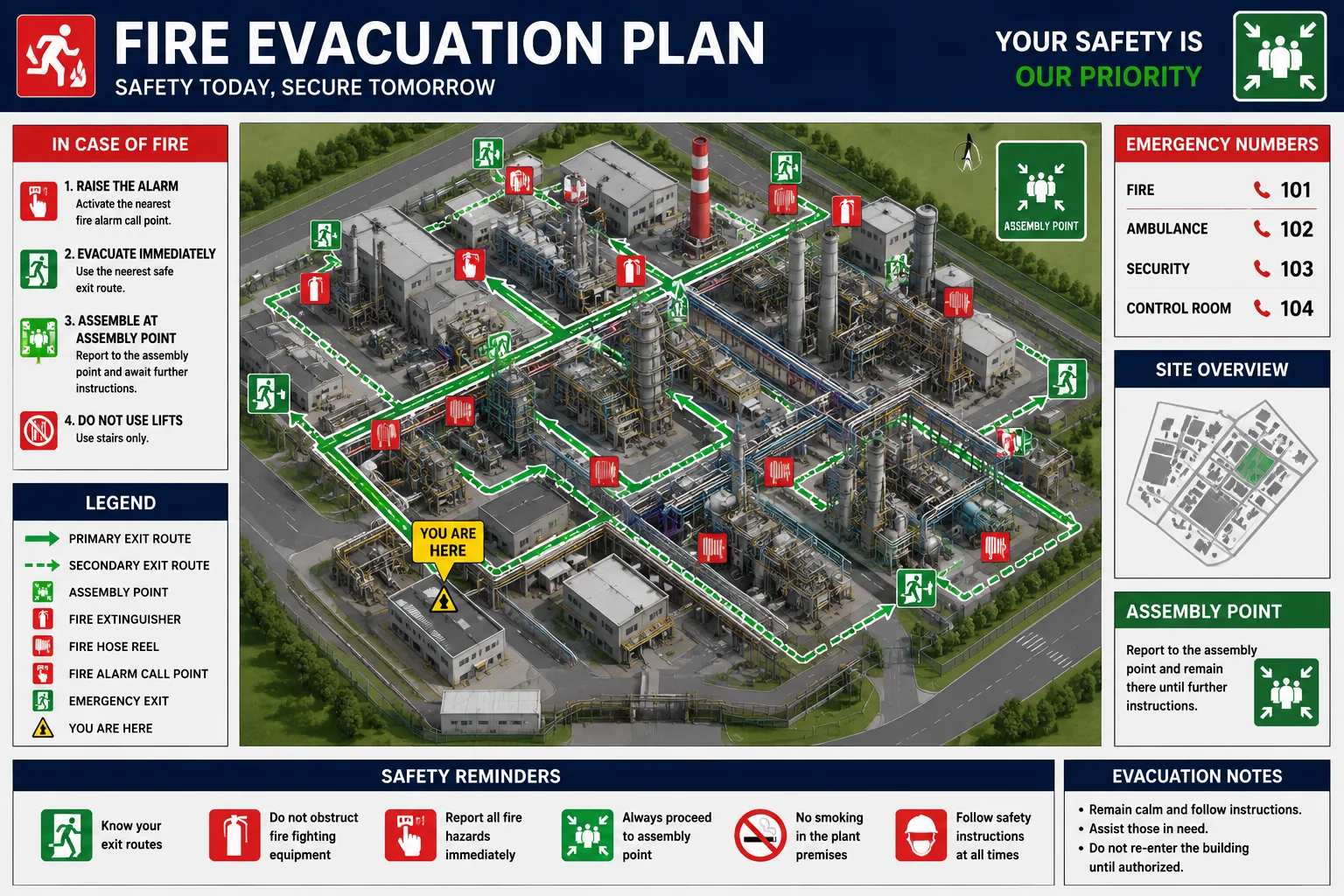
An industrial fire evacuation drawing—also referred to as an emergency evacuation drawing, evacuation map, or egress route drawing—is a purpose-built safety diagram posted at strategic locations across a facility. Its primary objective is to orient building occupants, identify designated escape pathways, locate essential firefighting and life-safety equipment, and direct personnel safely toward exterior emergency exits and designated assembly points.
An evacuation drawing differs fundamentally from general architectural floor plans, civil plots, structural framing drawings, or piping general arrangement (GA) drawings. Standard construction drawings feature dense dimensions, column grids, piping runs, and trade callouts. While essential for builders, this detail creates visual clutter in an emergency.
In contrast, a fire evacuation CAD drawing filters out non-essential construction geometry, removing secondary utilities and interior details. What remains is a high-contrast layout accentuating perimeter walls, primary corridors, emergency exit doors, protected stairwells, and vital emergency assets. This clear visual hierarchy allows occupants to understand their egress options in seconds.
2. What Information Is Typically Shown on an Evacuation Drawing?
While drawing content depends on facility hazards, occupancy, and jurisdiction, professional evacuation drawings typically include:
- Current Floor Layout: Simplified building envelope, primary dividing walls, major equipment footprints, and main circulation paths.
- Designated Emergency Exits: Clearly highlighted exterior discharge doors, fire-rated stairwells, and horizontal exits through fire barriers.
- Primary and Alternative Routes: Continuous paths showing approved egress travel, distinguishing primary from secondary routes.
- Direction of Travel: Directional arrows guiding occupants away from hazard zones toward exits.
- Assembly and Muster Points: Designated exterior assembly areas for post-evacuation roll-call accounting.
- Orientation Marker ("You Are Here"): A prominent marker indicating the drawing's physical mounting position.
- Life-Safety Equipment: Standard symbols for extinguishers, alarm pull stations, hose reels, eyewash units, and first-aid kits.
- Legends and Metadata: A complete visual key of symbols, paired with title block data including facility name, floor level, and revision details.
Drafting teams must not assume every drawing requires every item. Overloading a map with secondary valves or electrical panels impairs legibility; content must satisfy local safety requirements while keeping escape paths visually prominent.
3. Egress Route Mapping: Hierarchy, Continuity, and Legibility
The core of an evacuation drawing is egress path mapping. In facilities with process vessels, machinery, or automated racks, route planning requires technical discipline.
Primary and Alternative Routes: Egress planning requires route redundancy. Primary routes represent the most direct path to an approved exit, drafted using bold solid lines and prominent arrowheads. Alternative routes provide a secondary escape path if the primary corridor is blocked by fire, smoke, or debris, drafted with dashed or contrasting lines to maintain visual hierarchy.
Route Continuity and Exit Identification: Egress paths must lead continuously from occupied areas through exit access aisles and protected enclosures out to exterior assembly points. Mapped paths must never terminate in dead ends, and exits must be clearly distinguished from operational doors.
Avoiding Misleading Paths: Egress routes must never lead through transformer vaults, chemical storage, boiler rooms, or maintenance alleys. Mapped routes must reflect physical reality, accounting for railings, conveyor crossovers, and door clearances. Allowable travel distances and corridor dimensions are governed by adopted codes in the facility's jurisdiction.
4. Symbols, Legends and Visual Communication
During an emergency, written text can be difficult to interpret quickly under smoke or across language barriers. Consequently, fire safety drawings rely on standardized graphical symbols and disciplined visual communication.
Standard symbols on industrial fire evacuation CAD drawings include:
- Emergency Exits: Green graphical symbols (such as running-man glyphs) or bold "EXIT" markers designating exterior doors and stair towers.
- Fire Extinguishers: Standard red icons denoting portable extinguishers, with class indicators where relevant to chemical or electrical hazards.
- Alarm Points: Distinct symbols marking manual fire alarm pull stations and emergency communication devices.
- First-Aid and Safety Equipment: Green cross markers for first aid, and specific icons for eyewash and deluge safety showers.
- Assembly Areas and Directional Arrows: Standard muster station icons and unambiguous directional travel arrows.
- Orientation Indicator: A bold, high-contrast "You Are Here" focal point anchoring the observer's physical location.
Consistency across the facility is paramount. Symbol sets must not vary between production areas and administrative annexes. Every symbol displayed on the floor plan must be defined in the drawing legend with matching geometry and color, sized to remain legible without obscuring plant geometry.
5. Floor Plan Orientation and the "You Are Here" Indicator
A major source of confusion in emergency drawings is incorrect orientation. Architectural drawings are standardly oriented "North-Up." While appropriate for construction, north-up orientation can cause severe spatial disorientation on wall-mounted evacuation maps.
The Principle of "Head-Up" Orientation: When viewing a wall-mounted plan, an individual's reference frame is egocentric: forward is down the hallway, left is physical left, and right is physical right. If a north-up plan is mounted on a south-facing wall, a left turn on paper corresponds to a right turn in reality. In an emergency, forced mental rotation introduces cognitive delay and risks wrong-way turns.
Professional workflows implement "head-up" or perspective-matched orientation. The drawing is rotated in CAD so that "up" on the sheet aligns with the viewer's physical sightline. If drawings are posted on opposite walls of the same hallway, two distinct CAD drawings must be produced—each rotated 180 degrees—so observers on either side experience an intuitive layout.
Each drawing must feature clear building, floor, and zone labels, alongside an unmistakable "You Are Here" indicator placed precisely at the mounting coordinate. Non-essential CAD layers—such as ceiling grids, conduit paths, and piping centerlines—must be purged so life-safety pathways remain visually dominant.
6. What Standards and Regulations May Apply?
When preparing industrial evacuation drawings, engineering teams must evaluate the regulatory frameworks governing their facility. Requirements depend on country, regional jurisdiction, occupancy classification, industrial hazards, and adopted building and fire codes.
OSHA Workplace Requirements (United States): In the United States, general industry workplace safety standards for emergency planning are established under OSHA 29 CFR 1910.38 (Emergency Action Plans). Under this regulation, covered employers must establish emergency action plans that include emergency evacuation procedures and exit-route assignments.
In its compliance guidance and OSHA Evacuation Plans and Procedures eTool, OSHA notes that floor plans and workplace evacuation maps showing emergency exit routes and assembly areas are an effective means of communicating exit assignments to employees. OSHA regulations do not prescribe a universal CAD drawing template, but clear, updated evacuation diagrams are widely recognized as an effective practice for meeting route communication duties.
International Standard ISO 23601:2020: Internationally, the International Organization for Standardization published ISO 23601:2020 (Safety identification — Escape and evacuation plan signs). This standard establishes formal design principles for displayed escape and evacuation plan signs in buildings. It provides recommendations for layout hierarchy, drawing scales, safety color usage (green for egress routes, red for fire equipment), ISO 7010 safety symbols, and "You Are Here" placement.
Important Jurisdictional Considerations: ISO 23601 provides standardized design principles rather than a universal legal mandate; its legal applicability depends on whether local regulations or corporate specifications adopt it. Similarly, OSHA defines overall emergency action plan duties without mandating a singular drawing format. Regional codes like the IBC, IFC, and NFPA 101 govern exit capacities, travel distances, and signage. Plant teams must always verify adopted codes, local fire authority requirements, and project specifications for their specific facility.
7. Common Problems in Industrial Fire Evacuation Drawings
In active plants, fire evacuation drawings frequently degrade due to physical modifications and documentation neglect. Common engineering and documentation problems include:
- Outdated Floor Plans: Partitions shifted, modular offices built, or machinery installed without updating base drawings.
- Blocked or Changed Routes: New machinery, conveyor lines, or warehouse racking placed across designated egress pathways.
- Incorrect Equipment Locations: Extinguishers or pull stations relocated during maintenance while drawings show obsolete positions.
- Missing or Misidentified Exits: Service doors incorrectly labeled as emergency exits, or newly added exits omitted.
- Unclear Route Arrows: Overlapping or conflicting arrows pointing into dead ends or hazard areas.
- Poor Orientation: North-up drawings posted indiscriminately without perspective rotation, confusing occupants during an evacuation.
- Inconsistent Symbols and Clutter: Mismatched symbol sets across buildings and excessive construction linework obscuring life-safety data.
- Obsolete Revisions: Contradictory drawing revisions posted across adjacent zones, undermining drawing credibility.
8. How Fire Evacuation Drawings Are Prepared and Reviewed
Developing accurate, professional fire evacuation drawings requires a structured engineering workflow:
1. Intake & Baseline Review
Collect available architectural floor plans, civil layouts, equipment general arrangements, and facility EHS emergency documents.
2. CAD Cleansing & Layer Filtering
Strip construction dimensions, structural grids, and piping details. Isolate perimeter walls, primary partitions, and corridors on dedicated CAD layers.
3. Emergency Data Verification
Cross-reference exit doors, stairwells, fire extinguishers, alarm pull stations, and eyewash units against verified facility records.
4. Route Mapping & Arrow Placement
Draft primary and alternative egress paths using standardized line weights, verifying continuous routing to exterior exit discharges.
5. Symbology & Legend Integration
Place standardized safety symbols at verified coordinates and create an exhaustive drawing legend matching all colors and line types.
6. Perspective Rotation ("You Are Here")
Generate rotated sheet views matched to specific wall-mounting sightlines and position the "You Are Here" marker accurately.
7. Multi-Discipline Engineering Review
Review draft package against project requirements, checking exit continuity, legend completeness, and drafting accuracy.
8. Revision-Controlled Deliverable Issuance
Export drawings into native DWG, layered PDF, and display print formats, recording final issues in the master drawing register.
Engineering teams must maintain transparency: drawings prepared from client records should be documented accordingly, distinguishing desk drafting from physical on-site walkdowns.
9. When CAD-Based Fire Evacuation Drawings Are Useful
Standardized CAD-based fire evacuation drawings provide essential utility across a diverse range of industrial operating environments:
- Manufacturing and Assembly Plants: Production floors with robotic cells and machinery requiring clearly marked pedestrian escape paths.
- Chemical and Process Facilities: Processing units with hazardous material storage, elevated decks, and zoned muster stations.
- High-Bay Warehouses: Expansive racking layouts and forklift aisles where spatial disorientation is a known hazard during power failures.
- Pharmaceutical and Cleanroom Suites: Pressure-zoned facilities where emergency egress must navigate airlocks and gowning rooms.
- Industrial Control Rooms and Offices: Technical offices and operations centers located within plant battery limits.
- Plant Revamps and Modernizations: Facility reconfigurations that require updating legacy emergency documentation.
- Drawing Digitization Programs: Transforming scanned or paper plans into editable CAD models via CAD Conversion Services.
- Plant Layout Integration: Coordinating egress corridors with machinery footprints through specialized Industrial Plant Layout Design Services.
10. Fire Evacuation Drawing Services at Port AI Engineers
Port AI Engineers delivers professional CAD drafting and engineering documentation support to EPC contractors, industrial plant operators, and engineering consultants. Our drafting team specializes in preparing clear, standardized, revision-controlled fire evacuation drawings tailored to demanding industrial environments.
Through our specialized Fire Evacuation Drawing Services, we support clients with:
- CAD-based fire evacuation drawing preparation and emergency exit layouts.
- Egress route mapping, primary and alternative path design, and directional arrows.
- Perspective-matched "You Are Here" drawing creation for specific mounting locations.
- Symbol standardization and comprehensive legend development across industrial campuses.
- Drawing conversion from scanned PDFs or paper blueprints to native CAD via CAD Conversion Services.
- Drawing revision maintenance, layer standardization, and drawing register coordination.
Our workflows emphasize technical discipline, visual clarity, and alignment with client drafting requirements, delivering reliable safety documentation for operations and compliance reviews.
Conclusion
In industrial facilities, an accurate, legible fire evacuation drawing is an essential component of life safety and emergency response preparedness. When alarms sound, plant personnel and emergency responders rely on these schematics to make swift, safe egress decisions. Outdated floor layouts, cluttered linework, ambiguous route arrows, and inverted orientations introduce critical confusion when seconds count.
By applying clear visual hierarchies, primary and secondary egress paths, perspective-matched orientations, and disciplined revision control, industrial facilities can establish life-safety documentation that truly protects personnel. Because regulatory requirements, building codes, and safety standards vary across jurisdictions and facility occupancies, engineering teams must always coordinate their evacuation drawings with applicable local authorities and adopted codes.
To update your plant's emergency evacuation documentation or convert legacy floor plans into professional, revision-controlled CAD drawings, explore our Fire Evacuation Drawing Services or contact the engineering drafting team at Port AI Engineers today.
More from Port AI Engineers
Explore related engineering and CAD insights.