
PFD vs. P&ID: Key Differences and the Engineering Design Handoff
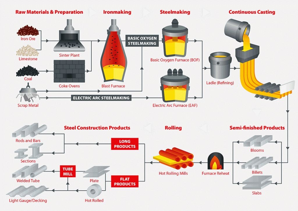
In industrial plant engineering, few engineering deliverables are as foundational—or as frequently misunderstood by early-stage project stakeholders—as the Process Flow Diagram (PFD) and the Piping and Instrumentation Diagram (P&ID). While both diagrams map the physical and functional architecture of chemical, petrochemical, manufacturing, and energy facilities, they serve fundamentally different purposes at distinct phases of the engineering lifecycle.
A Process Flow Diagram establishes the thermodynamic and mass balance foundation of a facility, defining what happens to raw materials, fluids, and utilities as they move across unit operations. In contrast, a Piping and Instrumentation Diagram serves as the comprehensive mechanical and operational master plan, detailing how that process will be physically piped, isolated, monitored, and automated in real-world equipment and control systems.
Confusing these two documents or rushing the transition between them is one of the most common causes of engineering change orders, piping clashes, and field rework during construction. Understanding the distinct role of each diagram—and managing the engineering design handoff between them with procedural rigor—is essential for engineering consultants, EPC contractors, and plant owners alike.
1. What Is a Process Flow Diagram (PFD)?
A Process Flow Diagram (PFD) is a schematic drawing that illustrates the sequence of equipment, major chemical transformations, and bulk fluid transport within an industrial process unit. Developed primarily during conceptual design and Front-End Engineering Design (FEED), the PFD illustrates the continuous flow of process fluids, energy balances, and operating envelopes without burdening the viewer with mechanical details.
On an engineering-grade PFD, major process equipment is prominently depicted using standardized graphical symbols. This includes distillation columns, reactors, pressure vessels, shell-and-tube heat exchangers, storage tanks, multi-stage compressors, and primary process pumps. Minor equipment, individual auxiliary components, and redundant standby units (such as spare pumps or utility bypasses) are typically omitted to maintain macro-level clarity.
Crucially, the PFD incorporates process stream numbering tied directly to heat and material balances (HMB). Accompanying stream tables specify fundamental process variables for each designated stream, including design operating temperatures, normal operating pressures, total mass flow rates, volumetric capacities, vapor-liquid fractions, fluid density, and primary chemical compositions.
Major utility inputs—such as high-pressure steam, cooling water supply and return, fuel gas, refrigeration loops, and plant compressed air—are indicated at the boundary limits of major equipment. By focusing strictly on process feasibility, system continuity, and thermodynamic stability, the PFD forms the core baseline from which all detailed mechanical engineering and equipment procurement datasheets originate.
2. What Is a Piping and Instrumentation Diagram (P&ID)?
A Piping and Instrumentation Diagram (P&ID)—also referred to as a Process and Instrumentation Diagram or Engineering Flow Sheet—is the definitive technical schematic that details the complete physical piping, mechanical components, field instrumentation, control loops, and safety systems required to construct, commission, and operate the plant.
Unlike the conceptual PFD, the P&ID depicts every mechanical pipeline that will be fabricated in the field or shop. Each line is identified with a standardized alphanumeric code indicating nominal pipe size (NPS or DN), fluid service code, line sequential number, piping material specification class, insulation type and thickness, and heat tracing requirements (electric or steam). Reducers, flow direction arrows, slope designations, and physical specification breaks (such as changes in pressure rating or metallurgy) are explicitly documented.
The P&ID also details all operational and isolation valves, identifying whether each is a gate, globe, ball, butterfly, diaphragm, or check valve. Automated control valves and emergency shutdown valves (ESDV) are displayed with their actuator types and fail-safe operational positions (Fail Open - FO, Fail Closed - FC, or Fail Locked - FL). Essential piping features such as high-point vents, low-point drains, sample connections, temporary strainers, blind flanges, and spectacle blinds are fully shown to support hydrostatic pressure testing and operational isolation.
Furthermore, the P&ID illustrates the entire instrumentation and control framework. Field transmitters (flow, pressure, temperature, level), control room distributed control system (DCS) nodes, local indicator gauges, programmable logic controller (PLC) interlocks, safety relief valves (PSV), and automated safety shutdown sequences are mapped using standardized instrumentation symbology. As a result, the P&ID serves as the shared reference document across process, piping, electrical, instrumentation, civil, constructability, and operations disciplines throughout the entire asset lifecycle.
3. PFD vs. P&ID — Side-by-Side Comparison
To illustrate the technical boundaries between the two documents, the following comparison highlights key engineering attributes across both deliverables:
| Characteristic | Process Flow Diagram (PFD) | Piping & Instrumentation Diagram (P&ID) |
|---|---|---|
| Primary Purpose | Defines process chemistry, mass/energy balances, and core system operating envelopes. | Defines complete mechanical piping, instrumentation, control loops, and physical equipment connections. |
| Level of Detail | Macro-level / conceptual; omits minor lines, utility branches, and auxiliary valves. | Comprehensive / mechanical; details every line, valve, instrument, nozzle, and drain point. |
| Equipment Shown | Major process equipment with basic tags, operating duties, and preliminary design capacities. | All process, utility, and auxiliary equipment, including spares, nozzles, foundation tags, and internals. |
| Piping Representation | Primary process streams only; depicted as schematic flow lines without size or spec class. | Every physical pipe line with exact diameter, pipe spec, material class, insulation, and tracing. |
| Instrumentation | Only critical primary control loops that govern fundamental process stability. | Complete field instrumentation, transmitters, local gauges, safety interlocks, and DCS I/O tags. |
| Valves & Fittings | Major control valves directly affecting process flow; manual isolation valves omitted. | All manual isolation, control, check, relief (PSV), drain, vent, and sampling valves. |
| Process Data Included | Stream tables with operating temperature, pressure, flow rate, composition, and enthalpy. | Process data generally omitted; replaced with mechanical design pressure, test pressure, and line specs. |
| Typical Engineering Stage | Conceptual Engineering and Front-End Engineering Design (FEED). | Detailed Engineering, Procurement, Construction, Commissioning, and Plant Operation. |
| Primary Stakeholders | Process engineers, project managers, client leadership, financial estimators. | Piping designers, instrumentation engineers, safety teams (HAZOP), fabricators, operators. |
*Note: Applicable project, client, industry, and drafting standards may vary depending on jurisdiction, facility operating envelope, and contractual specifications (e.g., ISA-5.1, ISO 10628, ASME, or proprietary owner-operator specifications).
4. How Information Moves From PFD to P&ID
The transition from a validated PFD to an approved P&ID represents the critical bridge between chemical/process conceptualization and physical mechanical design. This engineering handoff is not an abrupt shift, but an iterative, phased progression governed by multi-discipline coordination:
Step 1: Process Simulation & Flow Definition
Process engineers perform steady-state or dynamic process simulations to establish heat and material balances, thermodynamic limits, and stream properties, documenting these in the approved PFD package.
Step 2: Equipment Tagging & Nozzle Sizing
Equipment tags from the PFD are locked and transferred to the mechanical equipment list. Mechanical and piping engineers define specific nozzle schedules, elevation datum lines, design pressures, and flange ratings.
Step 3: Line Sizing & Piping Material Specifications
Process fluid streams from the PFD are assigned individual line numbers based on velocity criteria and allowable pressure drops. Piping engineers assign appropriate piping material classes (metallurgy, pressure rating, gasket type) based on fluid corrosivity and operating conditions.
Step 4: Isolation, Vent, and Drain Philosophy Integration
Piping designers incorporate manual block valves, bypass lines, high-point vents, low-point drains, and utility flush connections necessary for plant maintenance, pressure testing, and chemical decontamination.
Step 5: Control Loop & Safety Interlock Development
Instrumentation and control engineers translate the high-level control strategies depicted on the PFD into full instrument loops, specifying transmitters, local indicators, automated control valves, interlocks, and emergency shutdown connections.
Step 6: Multidisciplinary Review & Baseline Issue
The preliminary P&ID is reviewed collaboratively across process, piping, instrumentation, structural, and safety disciplines before being issued for formal HAZOP (Hazard and Operability) analysis and detailed 3D CAD modeling.
While this progression illustrates the typical path of engineering data, the exact sequencing and sign-off gates vary depending on project execution contracts (EPC vs EPCM), client drafting standards, and industry-specific regulations.
5. What Should Be Established Before Detailed P&ID Development?
Attempting to draft detailed P&IDs while foundational process criteria remain fluid inevitably leads to severe drawing rework, mismatched line lists, and spatial clashes in 3D piping layouts. Engineering teams typically verify that key process parameters are stabilized before releasing drafting packages for detailed P&ID development:
- Frozen Process Simulation & Stream Tables: A finalized heat and material balance (HMB) confirming mass flow rates, operating temperatures, and maximum operating pressures across all primary circuits.
- Preliminary Mechanical Equipment List: Confirmed equipment naming conventions, capacities, materials of construction, and design pressure/temperature ratings.
- Battery Limits & Tie-In Identifiers: Clearly designated physical and contractual boundaries where process and utility streams enter or leave the battery limits of the unit.
- Piping Material Specifications (PMS): Approved piping classes defining pipe wall thicknesses, flange ratings, valve body materials, and gasket types compatible with process fluids.
- Project Line Numbering Philosophy: Established standards for designating line size, fluid service codes, unit area codes, sequential numbers, and insulation classifications.
- Basic Control & Overpressure Protection Philosophy: Defined functional logic for automated control loops, fail-safe valve orientations, pressure relief valve (PSV) discharge routings, and emergency depressurization paths.
- Project Drafting Standards & Symbology: Established symbol libraries and layer conventions adhering to project-specific criteria or recognized industry drafting standards.
These prerequisites represent sound engineering practice rather than an inflexible, universal mandate. In fast-track projects, partial P&ID drafting often proceeds concurrently with process refinement under disciplined management of change protocols.
6. Common Problems During the PFD-to-P&ID Handoff
When coordination breaks down between process engineering and mechanical drafting, systematic discrepancies can cascade into procurement and site construction. Industry experience highlights several recurring handoff challenges:
Tagging Inconsistencies
Equipment or instrument tags modified on process datasheets without updating the corresponding P&ID callouts lead to procurement errors, mislabeled purchase orders, and mismatched line lists.
Volatile Process Operating Data
Uncontrolled revisions to stream temperatures, pressures, or flow rates after line sizing has been frozen force downstream recalculation of pipe wall thickness and valve sizing.
Ambiguous Battery Limit Interfaces
Unclear line continuation references between adjacent P&ID sheets or offsite utility packages result in mismatched pipe diameters, uncoordinated spec breaks, and field fabrication clashes.
Late Instrument Loop Additions
Introducing safety interlocks or flow meters late in detailed engineering disrupts 3D piping routing, required straight-run pipe lengths, and pipe rack space allocations.
Unmanaged Redline Revisions
Informal verbal changes or untracked markup notes exchanged between disciplines without revision clouding and formal revision control create conflicting drawing sets in field offices.
Inadequate Multi-Discipline Review
Isolating P&ID drafting within CAD teams without periodic reviews by piping stress engineers and operations leads creates unvented dead-legs, pocketed lines, and unmaintainable valve heights.
7. How P&ID Review Supports Engineering Quality
A disciplined P&ID review process acts as the primary quality safeguard in plant design. By bringing together process, piping, instrumentation, civil/structural, and plant operations specialists, structured reviews ensure that conceptual process goals are safely and feasibly implemented:
During formal Hazard and Operability (HAZOP) and constructability reviews, multi-discipline teams systematically evaluate every line and node on the P&ID using guidewords (such as "No Flow," "More Temperature," or "Reverse Flow"). Potential operational deviations are scrutinized, verifying that adequate relief capacity, isolation boundaries, and automated interlocks exist to safeguard plant personnel and capital equipment.
Structured drawing check gates—moving from Issue for Review (IFR) to Issue for Design (IFD) and Issue for Construction (IFC)—maintain complete configuration control. Line-by-line verification confirms that piping specification breaks match flange ratings, valve accessibility aligns with operator walkways, and instrument impulse lines avoid vibration hazards. This rigorous checking culture minimizes the risk of costly on-site modifications and supports smooth commissioning.
8. When to Use PFD and When to Use P&ID
For project managers, plant owners, and non-specialist engineering leaders, knowing which document to reference depends directly on the decision context:
Turn to the Process Flow Diagram (PFD) when you need to:
- Understand overall chemical process transformations, flow pathways, and mass/energy balances.
- Evaluate plant throughput, utility requirements, operating envelopes, and overall system efficiency.
- Prepare conceptual project estimates, feasibility reports, and executive stakeholder presentations.
- Conduct early preliminary hazard reviews before mechanical details are established.
Turn to the Piping and Instrumentation Diagram (P&ID) when you need to:
- Procure valves, piping spools, field instruments, automated actuators, and specialty fittings.
- Perform detailed 3D piping routing, clash detection, and extraction of isometric fabrication drawings.
- Execute formal HAZOP, LOPA (Layer of Protection Analysis), and plant safety regulatory audits.
- Program DCS/PLC control logic, alarm setpoints, safety interlocks, and emergency shutdown matrices.
- Conduct pre-commissioning walkdowns, line pressure testing, and ongoing plant operations and maintenance.
9. PFD and P&ID Services at Port AI Engineers
Port AI Engineers delivers comprehensive industrial drafting and engineering documentation services to EPC contractors, industrial plant owners, and engineering consultants worldwide. Our drafting specialists and engineering teams support the entire design lifecycle, ensuring seamless alignment between conceptual process chemistry and detailed mechanical execution.
Our PFD Design & Drafting Services assist engineering teams during conceptualization and FEED, producing clean, standardized process flow diagrams complete with stream reference tables, boundary limits, and utility interfaces tailored to client drafting conventions.
For detailed engineering and plant modernization projects, our P&ID Design & Drafting Services deliver standards-compliant, intelligent piping and instrumentation diagrams. We handle line sizing integration, valve tagging, instrument loop mapping, safety relief representation, and as-built redline drafting, coordinating closely with related disciplines such as General Arrangement Drawing Services and Industrial Plant Layout Design Services.
Conclusion
In industrial plant engineering, the Process Flow Diagram and the Piping and Instrumentation Diagram are not competing representations of a facility; they are complementary, sequential stages of an evolving engineering design. The PFD defines the operating concept, establishing what the plant must achieve thermodynamically and chemically. The P&ID defines the mechanical reality, detailing how that process will be safely contained, routed, monitored, and operated.
By treating the PFD-to-P&ID transition as a formal engineering handoff—anchored by stabilized process data, disciplined tagging standards, and multi-discipline review gates—engineering organizations minimize rework, protect project schedules, and establish a dependable technical foundation for fabrication, construction, and safe plant operations.
More from Port AI Engineers
Explore related engineering and CAD insights.